| Brand | Rw Energy |
| Model NO. | 0.4kV/6kV/10kV Filter capacitor (FC) |
| Rated voltage | 6kV |
| Series | FC |
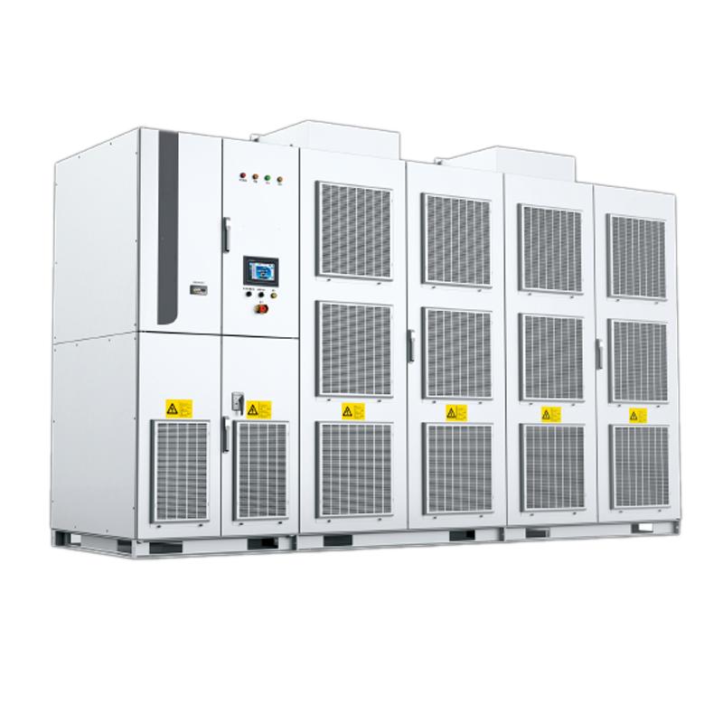
Product overview
Filter capacitors are classic passive reactive power compensation and harmonic management devices in medium and low voltage distribution networks. Their core functions are to provide capacitive reactive power, improve the power factor of the power grid, and at the same time, form a filter circuit in series with reactors to specifically suppress certain harmonics (such as 3rd, 5th, and 7th harmonics), reducing the impact of harmonic pollution on the power grid and electrical equipment. The product has a simple and compact structure, is cost-effective, and easy to maintain, without the need for complex control modules. It is suitable for steady-state load scenarios, can effectively reduce power grid losses, avoid reactive power fines, and stabilize the supply voltage. It is a cost-effective choice for power quality optimization under limited budgets or simple working conditions, and is widely applicable to various industrial and civil power distribution systems.
System Structure and Working Principle
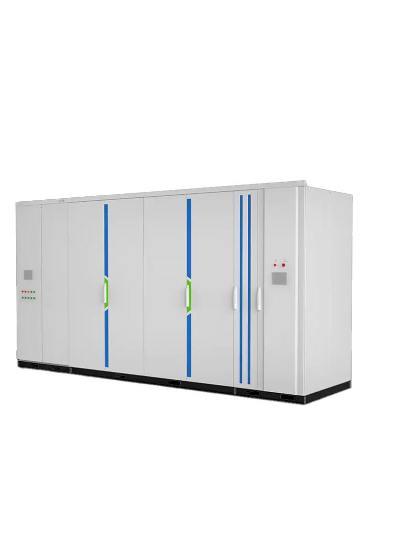
Core Structure
Capacitor unit: Adopts metallized film or oil-paper insulation structure, featuring low loss, high insulation strength, and long service life. Single or multiple units are connected in parallel to form a capacity module to meet different reactive power compensation requirements.
Filter reactor: Connected in series with the capacitor to form a filter circuit with a specific resonant frequency, specifically absorbing certain harmonics in the power grid (such as 3rd, 5th, and 7th harmonics) to avoid harmonic amplification.
Protection unit: Integrates fuses, discharge resistors, and overvoltage protectors to achieve overcurrent protection, rapid discharge after power failure, and overvoltage protection, ensuring the safety of equipment and personnel.
Cabinet structure: Outdoor protective cabinets meet the IP44 standard, and indoor ones meet IP30, with dustproof, moisture-proof, and anti-condensation functions, suitable for different installation environments.
Working Principle
In the distribution network, filter capacitors are put into operation to provide capacitive reactive power, offsetting the inductive reactive power generated by the load, thereby improving the power factor of the power grid (the target is usually ≥0.9) and reducing line losses caused by reactive power transmission. At the same time, the capacitor and the series reactor form an LC filter circuit, whose resonant frequency is consistent with the main harmonic frequencies in the power grid (such as 3rd, 5th, and 7th harmonics). When harmonic current passes through, the filter circuit presents low impedance characteristics, shunting and absorbing the harmonic current, preventing harmonics from propagating in the power grid, and finally achieving the dual effects of reactive power compensation and harmonic filtering, stabilizing the grid voltage and improving power quality.
Heat Dissipation Methods
Natural cooling (AN/Phase Transformation Cooling): The mainstream heat dissipation method, relying on cabinet ventilation and natural convection, suitable for medium and low-capacity products.
Forced air cooling (AF/Air Cooling): Equipped with cooling fans to enhance heat dissipation efficiency, suitable for the operation of equipment with large capacity or in high-temperature environments.
Primary diagram
Main Features
Economical and practical, with significant cost advantages: As a passive compensation device, it has low manufacturing cost, simple installation, no need for complex control and power electronic modules, and extremely low later maintenance costs, suitable for small and medium-sized customers with limited budgets and entry-level scenarios.
Integration of reactive power compensation and filtering: It can not only improve the power factor and reduce grid losses but also specifically suppress certain harmonics, avoiding damage to capacitors and other equipment caused by harmonics, and its functions meet the needs of steady-state loads.
Compact structure and flexible installation: Small in size and light in weight, it does not occupy a lot of space, supports indoor/outdoor installation, can be used alone or in multiple parallel groups, and is suitable for different capacity and scenario requirements.
Stable, reliable, and long service life: The core components are made of high-quality insulating materials, resistant to voltage fluctuations and environmental stress, with a normal operating life of 8-10 years; equipped with complete overcurrent and overvoltage protection, ensuring high operational safety.
Strong compatibility and wide adaptability: It can be directly connected to the distribution network without complex communication adaptation with the power grid, compatible with traditional power distribution systems and new energy supporting scenarios, and meets the IEC 60871 international standard.
Technical Parameters
Name |
Specification |
Rated voltage |
0.4kV±10%, 6kV±10%, 10kV±10%, 35kV±10% |
Frequency |
50/60Hz |
Filtering times |
3rd, 5th, 7th, 11th |
Dielectric loss tangent (tanδ) |
≤0.001 (25℃, 50Hz) |
Insulation class |
Class F and above |
Service life at rated voltage |
≥80000 hours (under normal operating conditions) |
Overvoltage withstand capacity |
Continuous operation at 1.1 times the rated voltage; operation at 1.3 times the rated voltage for 30 minutes |
Overcurrent withstand capacity |
Continuous operation at 1.3 times the rated current (including harmonic current) |
Discharge time |
Within 3 minutes after power failure, the residual voltage drops to below 50V |
Protection class (IP) |
Indoor IP30; Outdoor IP44 |
Storage temperature |
-40℃~+70℃ |
Operating temperature |
-25℃~+55℃ |
Humidity |
<90% (25℃), no condensation |
Altitude |
≤2000m (customizable above 2000m |
Seismic strength |
Grade Ⅷ |
Pollution degree |
Level Ⅳ |
Application Scenarios
Light industry and commercial buildings: Textile factories, food factories, office buildings, shopping malls, hotels, etc., to compensate for the reactive power of steady-state loads such as air conditioners, lighting, and water pumps, and improve the power factor.
Traditional industrial steady-state scenarios: Machine tool processing, small machinery manufacturing, pharmaceutical factories, etc., to suppress low-order harmonics generated by frequency converters and transformers, while optimizing the power factor and reducing energy consumption.
New energy supporting auxiliary: On the distribution network side of distributed photovoltaics and small wind farms, assisting SVG in steady-state reactive power compensation and harmonic filtering, reducing the overall investment cost.
Municipal and civil power distribution: Urban distribution networks, residential community power distribution systems, improving the power factor of the power grid, reducing line losses, and stabilizing residential electricity voltage.
Agricultural power distribution scenarios: Farmland irrigation, breeding bases, etc., to compensate for the reactive power of inductive loads such as water pumps and fans, avoiding insufficient power supply capacity caused by low power factors.
1.Capacity selection
Core formula: Q ₙ=P × [√ (1/cos ² π₁ -1) - √ (1/cos ² π₂ -1)] (P is the active power, π₁ is the power factor before compensation, and π₂ is the target power factor, usually ≥ 0.9).
Steady state load: Calculate the value according to the formula x 1.0~1.1 (with a small amount of redundancy reserved).
Containing a small amount of harmonic load: Calculate the value according to the formula multiplied by 1.2~1.3 (considering the capacity loss caused by harmonic current).
2.Filter frequency selection
Prioritize detecting the main harmonic components of the power grid: Determine the highest proportion of harmonics in the power grid through a power quality analyzer (such as 5 or 7 for frequency converter loads and 3 for lighting loads).
Targeted selection: For the main harmonics of 3rd order, choose 3rd order filter, and for 5th and 7th order, choose 5/7th order combination filter to avoid blind selection that may result in poor filtering effect or harmonic amplification.
What are the differences between SVG, SVC, and capacitor cabinets?
The three are the mainstream solutions for reactive power compensation, with significant differences in technology and applicable scenarios:
Capacitor cabinet (passive): The lowest cost, graded switching (response 200-500ms), suitable for steady-state loads, requires additional filtering to prevent harmonics, suitable for budget limited small and medium-sized customers and entry-level scenarios in emerging markets, in compliance with IEC 60871.
SVC (Semi Controlled Hybrid): Medium cost, continuous regulation (response 20-40ms), suitable for moderate fluctuating loads, with a small amount of harmonics, suitable for traditional industrial transformation, in compliance with IEC 61921.
SVG (Fully Controlled Active): High cost but excellent performance, fast response (≤ 5ms), high-precision stepless compensation, strong low-voltage ride through capability, suitable for impact/new energy loads, low harmonic, compact design, in line with CE/UL/KEMA, is the preferred choice for high-end markets and new energy projects.
Selection core: Choose capacitor cabinet for steady-state load, SVC for moderate fluctuation, SVG for dynamic/high-end demand, all of which need to match international standards such as IEC.
-
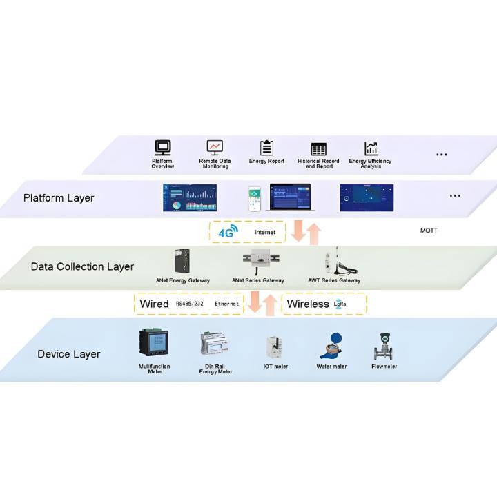
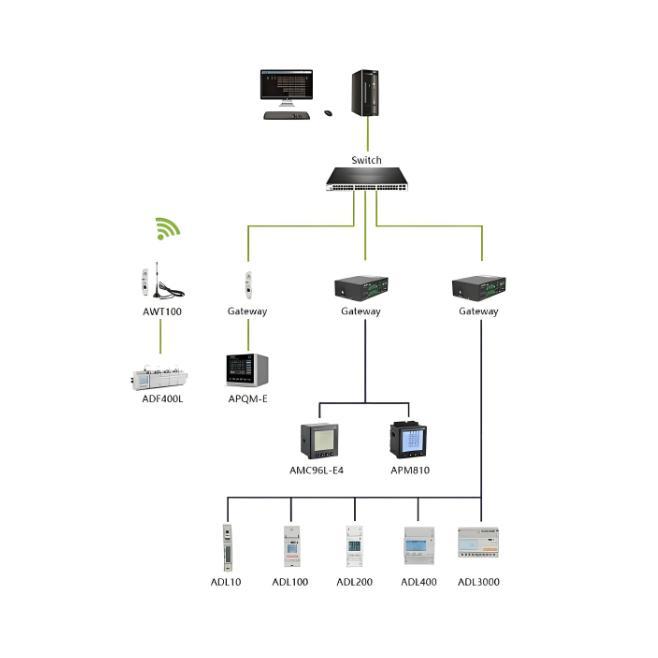 Integrated Smart Power Monitoring and Energy Efficiency Management SolutionOverviewThis solution aims to provide a smart power monitoring system (Power Management System, PMS) centered on end-to-end optimization of power resources. By establishing a closed-loop management framework of "monitoring-analysis-decision-execution," it helps enterprises transition from simply "using electricity" to intelligently "managing electricity," ultimately achieving safe, efficient, low-carbon, and economical energy usage goals. Core PositioningThe core positioning of this system is tRW Energy28/09-2025
 -
 A Novel Modular Monitoring Solution for Photovoltaic and Energy Storage Power Generation Systems1.Introduction and Research Background1.1 Current State of the Solar IndustryAs one of the most abundant renewable energy sources, the development and utilization of solar energy has become central to the global energy transition. In recent years, driven by policies worldwide, the photovoltaic (PV) industry has experienced explosive growth. Statistics indicate that China's PV industry saw a staggering 168-fold increase during the "12th Five-Year Plan" period. By the end of 2015, the installedRW Energy28/09-2025
 -
 Comprehensive Power Quality Diagnostic Expert System Solution1.Core PositioningThis solution is designed to provide a comprehensive, multi-dimensional power quality diagnostic expert system. It moves beyond traditional data acquisition and monitoring, deeply integrating advanced analysis and diagnostic functions, positioning itself as an enterprise's "Comprehensive Physician for Power Quality." It can accurately capture, deeply analyze, and intelligently diagnose various types of power quality issues within the electrical grid. It offers users a full-chaRW Energy28/09-2025
 -
 Ubiquitous Energy Management System Solution for Smart Cities and Integrated Parks1.Overview and Core PositioningThe core positioning of this system is: a comprehensive platform for the collaborative management and optimization of multiple energy flows, including water, electricity, gas, and heat. It goes beyond traditional power monitoring by breaking down energy data silos. Through integration, analysis, optimization, and prediction, it serves as an "energy brain" that provides panoramic visibility, intelligent decision-making, and deep value for various energy consumers sRW Energy28/09-2025
 -
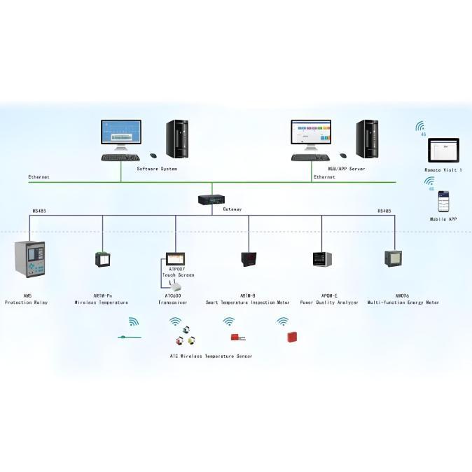
 Intelligent Power Monitoring: Smart Power Monitoring System Solution1.System OverviewCore Positioning: AI-Driven Adaptive Power Security GuardianThe Intelligent Power Monitoring system is a new-generation power monitoring solution designed for the future. It breaks through the limitations of "passive alarm" inherent in traditional monitoring systems. By integrating edge computing, cloud computing, and artificial intelligence technologies, it constructs an integrated active defense system encompassing "perception - analysis - decision - early warning." The coRW Energy28/09-2025
 -
 High-Precision Electrical Parameter Monitoring System Solution1.IntroductionWith the increasingly stringent requirements for power supply quality in high-end facilities such as precision manufacturing, medical diagnosis, and data centers, traditional power monitoring systems, due to their low sampling accuracy and weak data analysis capabilities, can no longer meet the demand for deep insight and precise management of power quality. In response, we are introducing a new generation High-Precision Electrical Parameter Monitoring System. With millisecond-lRW Energy28/09-2025